The most fundamental passive component — in every circuit ever built
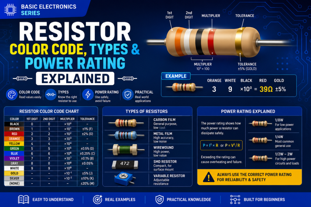
Table of Contents
Introduction
If there’s one component in every single electronic circuit, it’s the resistor. They limit current to protect LEDs and transistors, create voltage dividers for sensors, set gain in amplifiers, and pull signals to defined logic levels. This post covers reading the colour code, tolerances and power ratings, and the different types used in real designs.
Before learning resistors, read:
• Voltage, Current and Resistance
Part 1: Reading the Colour Code
Through-hole resistors have coloured bands that encode their value — a basic skill every electronics person needs.
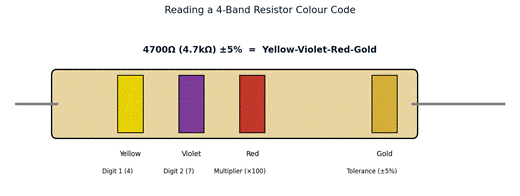
Figure 1 — Reading a 4-band resistor: digit, digit, multiplier, tolerance.
| Colour | Digit | Multiplier | Tolerance |
| Black | 0 | ×1 (10⁰) | — |
| Brown | 1 | ×10 (10¹) | ±1% (precision) |
| Red | 2 | ×100 (10²) | ±2% |
| Orange | 3 | ×1k (10³) | — |
| Yellow | 4 | ×10k (10⁴) | — |
| Green | 5 | ×100k (10⁵) | ±0.5% |
| Blue | 6 | ×1M (10⁶) | ±0.25% |
| Violet | 7 | ×10M (10⁷) | ±0.1% |
| Grey | 8 | ×100M | ±0.05% |
| White | 9 | ×1G | — |
| Gold | — | ×0.1 | ±5% |
| Silver | — | ×0.01 | ±10% |
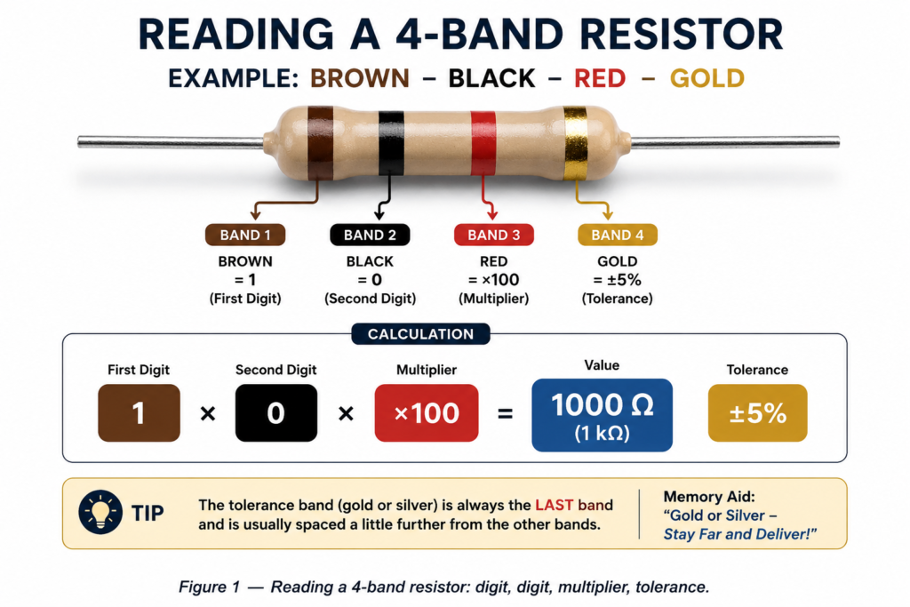
Reading a 4-Band Resistor
Band 1 = first digit, Band 2 = second digit, Band 3 = multiplier, Band 4 = tolerance.
| Example | Band 1 | Band 2 | Multiplier | Tolerance | Value |
| Yellow-Violet-Red-Gold | 4 | 7 | ×100 | ±5% | 4700Ω = 4.7kΩ ±5% |
| Brown-Black-Orange-Gold | 1 | 0 | ×1k | ±5% | 10,000Ω = 10kΩ ±5% |
| Red-Red-Brown-Gold | 2 | 2 | ×10 | ±5% | 220Ω ±5% |
| Brown-Black-Red-Brown | 1 | 0 | ×100 | ±1% | 1000Ω = 1kΩ ±1% |
💡 TIP
The gold or silver tolerance band is usually slightly separated from the rest, and is always the LAST band — read from the opposite end.
Memory aid: ‘Black Bears Rarely Offer Yummy Greens, But Vegetables Grow Wild’ = B,B,R,O,Y,G,B,V,G,W = 0-9.
Resistors with ±1% or better tolerance use 5 bands: Band 1, 2, 3 = three digits; Band 4 = multiplier; Band 5 = tolerance (brown = ±1%).
Part 2: Standard Values — the E-Series
Resistors aren’t available in every possible value — they come in standard series called E12, E24, E48, E96. The most common is E12 (±5% tolerance, 12 values per decade).
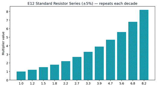
Figure 2 — The E12 series repeats these 12 multiplier values in every decade (×1, ×10, ×100…).
1.0, 1.2, 1.5, 1.8, 2.2, 2.7, 3.3, 3.9, 4.7, 5.6, 6.8, 8.2 — then ×10 for the next decade: 10, 12, 15, 18, 22, 27, 33, 39, 47, 56, 68, 82, 100, 120…
💡 TIP
When your calculation gives a non-standard value like 357Ω, choose the nearest E12 value — usually 330Ω or 390Ω.
For safety-critical components (LED current limiting), go slightly higher (more resistance = less current).
Part 3: Power Rating — This is Critical
Every resistor has a maximum power rating. Exceed it and the resistor overheats, changes value, and eventually burns or opens. Physical size is the clue — bigger means higher power rating.
| Physical Size | Power Rating | Use Case |
| Very small (1/8W) | 0.125W | SMD circuits, low-power signal paths |
| Small (1/4W) | 0.25W | Standard through-hole — most Arduino/sensor work |
| Medium (1/2W) | 0.5W | Slightly higher current circuits |
| Large (1W) | 1W | Motor drivers, power supplies, heaters |
| Very large (2W+) | 2W+ | Power circuits, dummy loads |
| Wirewound (many sizes) | 5-50W | Power resistors, current sensing, loads |
Example: a 470Ω resistor with 12V across it. P = V² ÷ R = 144 ÷ 470 = 0.306W. A standard ¼W (0.25W) resistor would overheat — you NEED at least a ½W resistor here. Rule of thumb: calculate the power, then choose a resistor rated at DOUBLE that value for safety margin. So 0.3W calculated → use ½W or 1W.
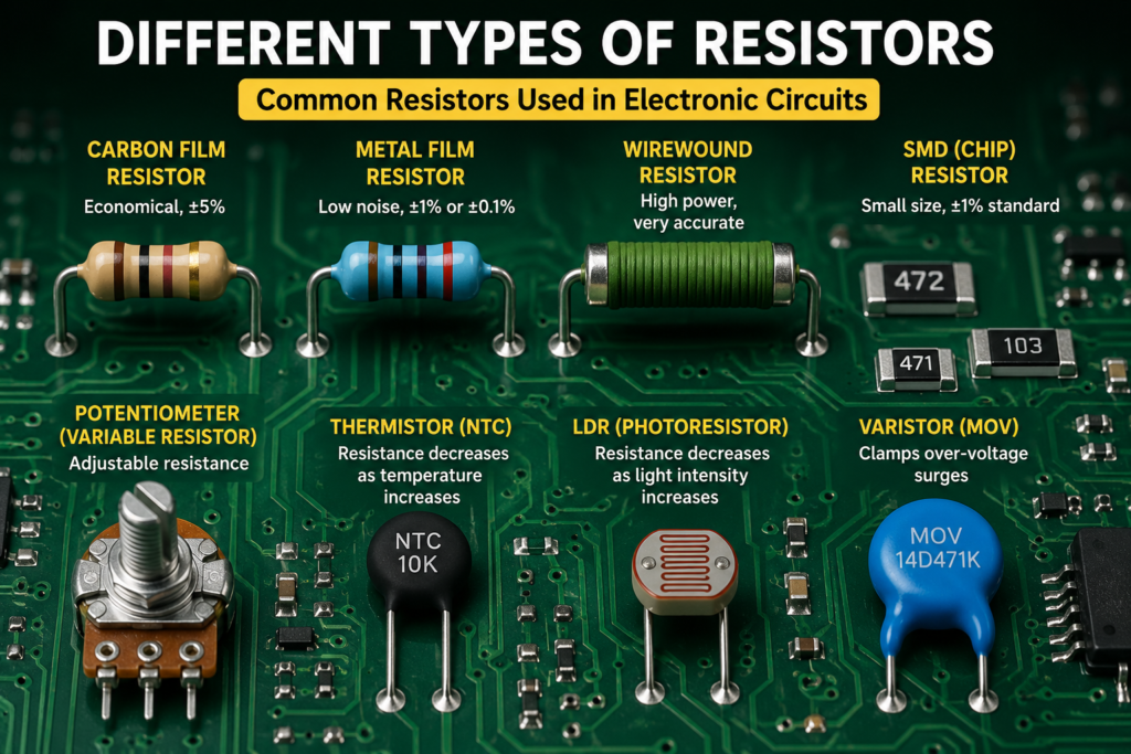
Part 4: Types of Resistors
| Type | Construction | Key Feature | Typical Use |
| Carbon Film | Carbon film on ceramic | Cheap, noisy, ±5% | General prototyping |
| Metal Film | Metal alloy film | Low noise, ±1% or ±0.1% | Precision circuits, audio |
| Wirewound | Resistance wire on a former | High power, very accurate | Power supplies, loads |
| SMD (chip) | Thick/thin film on ceramic | Tiny, ±1% standard | PCB production |
| Potentiometer | Wiper on resistive track | Adjustable resistance | Volume controls, calibration |
| Thermistor (NTC) | Semiconductor material | Resistance drops with heat | Temperature sensing |
| LDR | Photoconductive cell | Resistance drops with light | Light sensing |
| Varistor (MOV) | Zinc oxide | Clamps over-voltage | Surge protection |
Part 5: Pull-up and Pull-down Resistors
One of the most important applications of resistors in digital circuits is the pull-up or pull-down resistor, solving the ‘floating pin’ problem. A digital input pin with nothing connected floats between HIGH and LOW, picking up noise and giving random readings.
| Type | Connection | Default state | When button pressed |
| Pull-up | Pin → 10kΩ → VCC | HIGH (1) | LOW (0) — button connects pin to GND |
| Pull-down | Pin → 10kΩ → GND | LOW (0) | HIGH (1) — button connects pin to VCC |
💡 TIP
Arduino has built-in pull-up resistors (20-50kΩ) on all digital pins.
Enable with: pinMode(pin, INPUT_PULLUP);
This means you often don’t need an external pull-up resistor for buttons.
Applications of resistors
Example
| Device | Typical Resistor Use |
|---|---|
| Arduino | LED current limiting |
| Mobile charger | Voltage divider |
| Television | Biasing transistor circuits |
| Laptop | Pull-up resistors |
| Temperature sensor | Thermistor |
✅ QUICK RECAP
4-band colour code: D1, D2, Multiplier, Tolerance. Gold=±5%, Brown=±1%.
Standard E12 values: 1.0, 1.2, 1.5, 1.8, 2.2, 2.7, 3.3, 3.9, 4.7, 5.6, 6.8, 8.2.
Power rating: P = V²/R or P = I²×R. Choose resistor rated at 2× calculated power.
Physical size = power rating. Bigger body = handles more power.
Pull-up: connects pin to VCC via resistor. Default HIGH. Pull-down: to GND, default LOW.
Types: carbon film (cheap), metal film (precise), wirewound (high power), SMD (PCB).
Frequently Asked Questions
Q: What if I can’t tell which end of the resistor to start reading from?
A: Look for the tolerance band (usually gold or silver) — it’s always the last band, so start from the opposite end. It’s also often spaced slightly further from the others than the digit bands are from each other.
Q: Can I use a higher wattage resistor than needed?
A: Yes, always safe — a higher power rating simply means more margin and a physically larger component. You can never damage a circuit by over-specifying the power rating, only by under-specifying it.
Q: What’s the practical difference between ±5% and ±1% tolerance?
A: A ±5% 1kΩ resistor could actually measure anywhere from 950Ω to 1050Ω; a ±1% version is far tighter (990Ω-1010Ω). For LED current limiting ±5% is plenty; for precision analog circuits (op-amp gain, sensor references) ±1% or better matters.
Q: Why do pull-up resistors typically use 10kΩ instead of something smaller?
A: 10kΩ is a good compromise: small enough to firmly pull the pin to a defined state, but large enough that when the button/switch connects the pin to the opposite rail, only a small, safe current (a few hundred microamps) flows continuously.
Q: Is a thermistor a type of resistor or a separate component?
A: It’s technically still a resistor — its resistance is just deliberately sensitive to temperature by design, rather than treated as a fixed value. The same applies to LDRs (light-sensitive) and potentiometers (mechanically adjustable).
Q: How do I identify an SMD resistor’s value without bands?
A: Small SMD resistors use a 3 or 4-digit numeric code printed on the body, following the same ‘digits + multiplier’ logic as the 3-digit ceramic capacitor code shown in Post 6 — e.g. ‘472’ means 47 × 10² = 4700Ω.
🚀 NEXT UP
Post 6: Capacitors — What They Do, Types, and How to Read Values
Capacitors store charge, filter noise, and decouple power supplies — appearing in almost every circuit alongside resistors.