Most beginners only learn how to measure battery voltage, but a digital multimeter can also test current, resistance, continuity, diodes, LEDs, capacitance, and even frequency. Understanding these functions will save hours of troubleshooting and help you diagnose electronic circuits confidently.
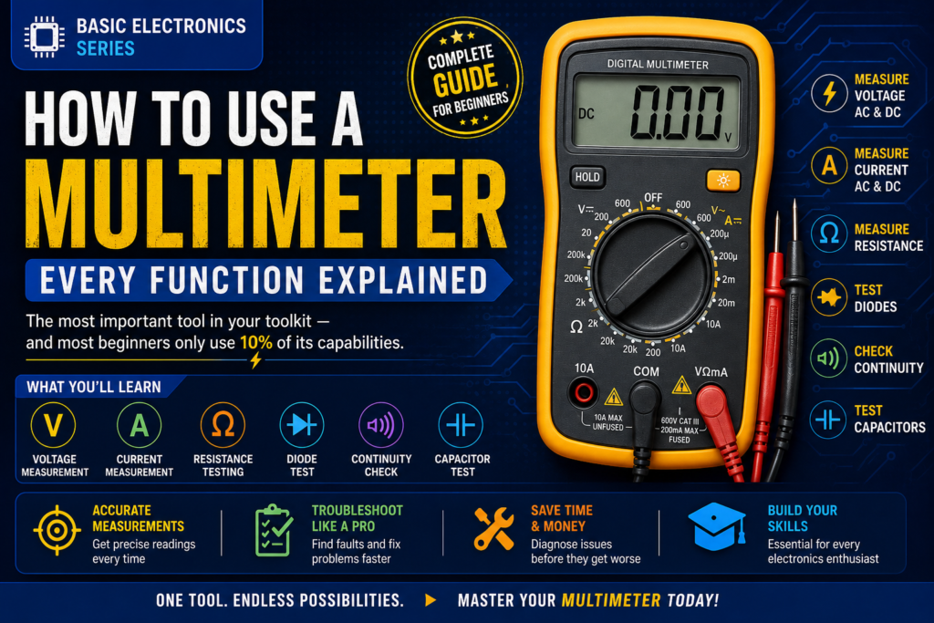
Table of Contents
Introduction
A multimeter is the Swiss Army knife of electronics — the first tool you pick up when something isn’t working, when you want to verify a voltage, check a component, or find where a circuit breaks. Most beginners learn only DC voltage measurement. This post covers every function, how to use each correctly, and the common mistakes that damage meters or give wrong readings.
By the end of this guide, you’ll be able to:
- Identify every part of a digital multimeter
- Measure DC and AC voltage safely
- Measure resistance accurately
- Test continuity and locate broken connections
- Measure current without damaging your meter
- Test diodes and LEDs
- Avoid the most common beginner mistakes
📝 NOTE
This post covers digital multimeters (DMM), which are what virtually everyone uses today.
Recommended beginner meter: Uni-T UT61E, Victor VC830L, or any Mastech meter.
Cost: ₹500-₹2000 for a reliable beginner meter. Don’t use the cheapest no-name meters for safety.
Part 1: Anatomy of a Multimeter
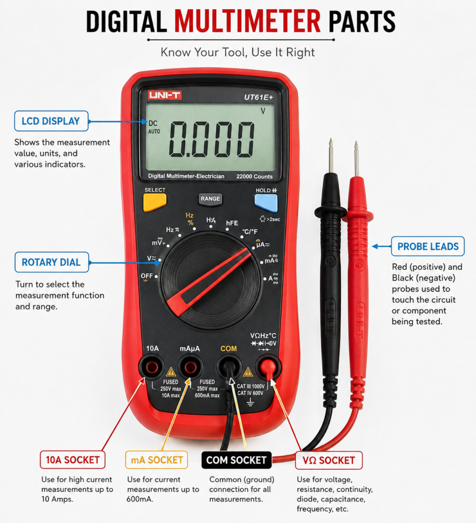
The Display
The LCD display shows the measurement value. Digit count indicates resolution: a ‘3½ digit’ meter shows up to 1999, a ‘4½ digit’ shows up to 19999. More digits = more precision.
The Rotary Selector
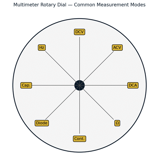
Figure 1 — A typical rotary dial and its common measurement positions.
- DC Voltage (V⎓): battery, Arduino pins, power supplies
- AC Voltage (V~): mains outlets, transformer outputs
- DC Current (A⎓ or mA): current in circuits
- Resistance (Ω): resistor values, checking components
- Continuity (🔊 with diode symbol): checking if a connection is complete
- Diode test (▷|): checking diodes and LEDs
- Capacitance (F): measuring capacitor values on some meters
- Frequency (Hz): measuring signal frequency on some meters
The Probes and Sockets
- COM (black probe): ALWAYS insert black probe here for every measurement
- VΩmA (red probe): for voltage, resistance, and milliamp measurements
- 10A or 20A (red probe): for measuring large currents only
⚠️ WARNING
NEVER measure current with the probe in the voltage/resistance socket — it will blow the internal fuse instantly.
NEVER measure mains AC voltage if you are not confident. Start with DC battery measurements.
Always check your probe sockets before measuring.
Part 2: Measuring DC Voltage
This is the most common measurement — battery levels, Arduino pin outputs, power supply outputs, sensor signals.
1. Set rotary dial to DC Voltage (V⎓)
2. If not auto-ranging: select a range HIGHER than the expected voltage (e.g. 20V range for a 9V battery). Auto-ranging meters select automatically.
3. Insert black probe into COM, red probe into VΩmA
4. Touch red probe to the positive point, black probe to ground/negative
5. Read the display
| Measurement | Expected reading | What a wrong reading means |
| Fresh AA battery | ~1.5V | < 1.2V = battery nearly dead |
| 9V block battery | ~9V | < 7V = replace battery |
| Arduino 5V pin | 4.8V-5.1V | Outside this = check power regulator |
| Arduino 3.3V pin | 3.2V-3.4V | Outside this = check regulator |
| Arduino HIGH output | ~5V | < 4V = overloaded pin (too much current draw) |
| Arduino LOW output | ~0V | > 0.5V = something wrong with the pin |
💡 TIP
If you measure a negative voltage (e.g. −9V when you expected +9V), your probes are reversed. Swap red and black — the reading is correct in magnitude.
Auto-ranging meters often show negative automatically to indicate probe polarity.
Part 3: Measuring Resistance
1. IMPORTANT: remove the component from the circuit first, or power it off completely.
2. Set dial to Ω (resistance)
3. Touch probes across the component (polarity doesn’t matter for resistors)
4. Read the display
⚠️ WARNING
NEVER measure resistance in a powered circuit. The meter injects its own small voltage to measure resistance — existing voltages in the circuit give wrong readings and could damage the meter.
| Reading | Meaning |
| 0.00Ω or OL near 0 | Short circuit — direct connection |
| OL or 1 (overload) | Open circuit — broken wire, no connection, or range too low |
| Close to marked value | Good component within ±5% or ±1% tolerance |
| Very different from marked | Damaged component, or component still in circuit |
Part 4: Continuity Testing
Continuity mode tells you if two points are electrically connected — the meter beeps if resistance is below ~30Ω. This is the fastest debugging tool you have.
- Check if a wire is broken (touch both ends — beep = good, no beep = broken)
- Trace PCB tracks (touch each end of a trace — beep = connected)
- Verify a switch is working (beep when closed, no beep when open)
- Check solder joints (beep = good connection, no beep = cold joint)
- Check fuses (beep = fuse is good, no beep = blown fuse)
💡 TIP
Continuity is the fastest way to debug a non-working circuit.
When a circuit doesn’t work: first check power (DC voltage), then check connections (continuity). 90% of problems are found this way.
Part 5: Measuring Current
Measuring current requires the meter to be in series with the circuit — you must break the circuit and insert the meter.
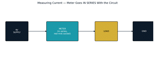
Figure 2 — To measure current, the meter must be inserted in series, not across the supply.
1. POWER OFF the circuit before rewiring
2. Move red probe to the mA socket (not the VΩ socket!)
3. Set dial to DC current (mA or A)
4. Break the circuit at the point you want to measure
5. Connect the meter in series: current flows INTO the red probe, OUT of the black probe
6. Power on the circuit and read the current
7. Remove the meter and reconnect the circuit when done
⚠️ WARNING
The current measurement puts very low resistance in the circuit.
If you accidentally use the current socket while probing a voltage source, you WILL blow the meter’s fuse. Fuses cost ₹20 but the lesson costs more — be careful.
Part 6: Diode and LED Testing
Diode test mode applies a small voltage and displays the forward voltage drop — this verifies a diode is working and identifies anode vs cathode.
| Diode type | Expected forward voltage reading |
| Silicon signal diode (1N4148) | 0.6 – 0.7V |
| Silicon rectifier diode (1N4007) | 0.7 – 1.0V |
| Red LED | 1.8 – 2.0V |
| Green LED | 1.9 – 2.1V |
| Blue/White LED | 2.8 – 3.4V |
| Schottky diode | 0.2 – 0.4V |
| OL (overload) | Probes reversed, or diode is open (failed) |
| 0.000V | Diode is shorted (failed) |
💡 TIP
When testing an LED in diode mode, it will very dimly glow — this is normal, the meter current is too small to light it brightly.
It confirms the LED is good and tells you which leg is which: LED glows when red probe is on anode, black on cathode.
✅ QUICK RECAP
DC Voltage: red to positive, black to GND. Most common measurement.
Resistance: power off first. Never measure in a live circuit.
Continuity: instant connection check. Beep = connected.
Current: must be in SERIES. Move probe to current socket first.
Diode test: shows forward voltage. LEDs glow dimly when working.
COM socket always gets black probe. Match red probe socket to measurement type.
Auto-ranging meters are safer for beginners — no need to pre-select range.
Frequently Asked Questions
Q: Why did my multimeter show ‘OL’ when measuring a resistor?
A: OL (overload) usually means the reading is outside the selected range, or there’s no continuous path. On a non-auto-ranging meter, try a higher resistance range. If the range is already high enough, the component may be open (failed) or your probes aren’t making good contact.
Q: Can I damage my multimeter by using the wrong mode?
A: Yes — the most common damage is blowing the internal fuse by measuring current (or a low-resistance path) while accidentally in a voltage-measuring configuration, or by having the red probe in the mA/A socket while measuring a voltage source directly.
Q: Do I need an expensive multimeter to start?
A: No. A ₹500-₹2000 meter from a known brand (Mastech, Victor, Uni-T) is entirely adequate for hobby and even much professional work. What matters more is understanding each function correctly.
Q: Why does my meter show a small non-zero resistance even with the probes touching each other?
A: This is normal lead resistance, typically 0.1-0.5Ω from the probe wires themselves. For most component checks this is negligible, but for very low-value resistors it’s worth zeroing it out or accounting for it.
Q: What’s the difference between continuity mode and resistance mode?
A: Both measure resistance, but continuity mode is optimised for a fast audible pass/fail check (beep below ~30Ω) rather than showing a precise numeric value, making it faster for tracing wires and connections.
Q: My auto-ranging meter takes a second to settle — is that normal?
A: Yes. Auto-ranging meters test several ranges internally before settling on the best one, which takes slightly longer than a manual-range meter already set correctly. This is a normal trade-off for convenience.
🚀 NEXT UP
Post 5: Resistors — Reading Color Codes, Types, and When to Use Them
You’ve been using resistors throughout this series — now we go deep: colour codes, standard values, power ratings, and types.