POST 11 ● SERIES 1: ELECTRONICS BASICS ● 10 min read
Breadboard Basics are one of the first skills every electronics beginner should master. A breadboard is a reusable prototyping platform that lets you build circuits by pushing components and wires into holes without soldering. Understanding Breadboard Basics helps you read schematics, build reliable circuits, troubleshoot wiring problems, and prototype projects quickly. Every electronics hobbyist starts with a breadboard, and many professional engineers still use breadboards for rapid testing before designing a PCB.
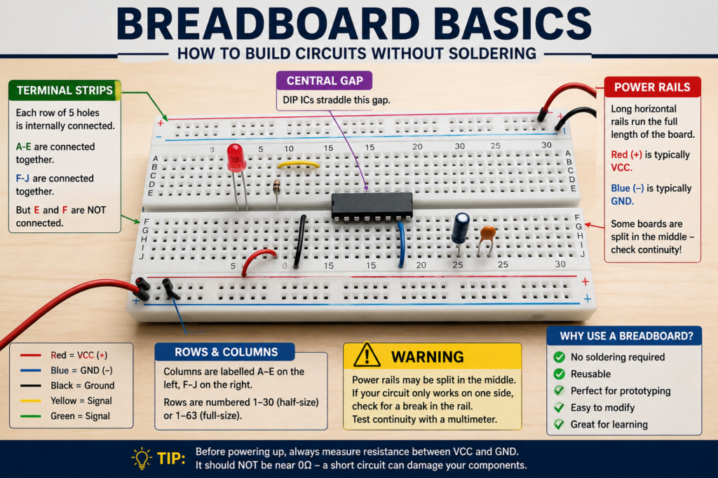
Table of Contents
Introduction
A breadboard is a reusable prototyping platform that lets you build circuits by pushing components and wires into holes — no soldering required. Every electronics hobbyist starts here, and many professional engineers still use breadboards for quick prototyping. Understanding exactly how a breadboard works internally prevents the most common mistakes and makes circuit building much faster.
Part 1: Breadboard Basics: How a Breadboard Works Internally
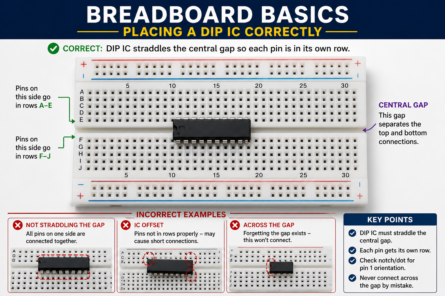
Figure 1 — Breadboard internal connections: rows of 5 connected holes, a central gap, and continuous power rails.
The Terminal Strips (Main Area)
The main area consists of rows of 5 connected holes, separated by a central gap. Holes within the same row of 5 are all electrically connected internally. The central gap separates the top and bottom halves — DIP ICs straddle this gap.
- Columns are labelled A-E on the left half, F-J on the right half.
- Rows are numbered 1-30 (half-size) or 1-63 (full-size).
- Holes A1, B1, C1, D1, E1 are all connected. F1, G1, H1, I1, J1 are all connected.
- But A1 and F1 are NOT connected — the central gap separates them.
The Power Rails
Along each side of the breadboard are two long horizontal rails marked + (red) and − (blue). Each rail is one continuous connected strip running the full length of the board. Use these for VCC (+) and GND (−).
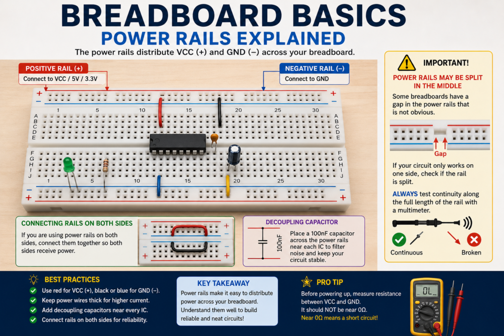
⚠️ WARNING
On some breadboards, the power rails are split in the middle.
There’s a gap halfway along the rail that isn’t obvious.
If your circuit only works on one side of the board, check if the rail has a break.
Test continuity along the full rail length with a multimeter.
Part 2: Best Practices for Breadboard Circuits
Power Distribution
1. Connect the positive rail to VCC/5V/3.3V at one end. Connect negative rail to GND.
2. If using both rails on both sides, run a wire connecting the left + rail to the right + rail, and left − to right −.
3. Add a 100nF decoupling capacitor across the rails near each IC.
Component Placement
1. DIP ICs (chips with two rows of pins): place them straddling the central gap. Each pin gets its own row.
2. Keep related components close together — short wire paths reduce noise.
3. Use different coloured wires for different signals: red = VCC, black = GND, other colours = signals.
4. Keep wires as short as possible and flat against the board — long wires pick up interference.
Common Mistakes
- Pushing two wires into the same hole instead of adjacent holes in the same row — won’t connect properly.
- Connecting across the central gap (e.g. E1 to F1) — these are NOT connected, you need a wire.
- Using the bottom holes on an IC’s row for a connection that should go to a different component.
- Forgetting to connect power rails together if you’re using rails on both sides.
- Using very short wire stubs that accidentally connect to neighbouring rows.
Part 3: Translating a Schematic to Breadboard
1. Place the main ICs first, straddling the central gap.
2. Connect power: VCC and GND to the power rails, then short wires from rails to IC power pins.
3. Add decoupling capacitors (100nF) between each IC’s VCC and GND pins.
4. Connect the signal wires — trace each net from the schematic and wire it up.
5. Add passive components (resistors, capacitors) in the remaining rows.
6. Double-check every connection against the schematic before powering up.
💡 TIP
Before powering up a new breadboard circuit, measure resistance between VCC and GND.
It should NOT be near 0Ω — a reading close to 0Ω means you have a short circuit somewhere.
Find the short before applying power — it will save components (and possibly your Arduino).
Part 4: Breadboard Limitations
- High resistance and parasitic capacitance in the contacts — bad for high-frequency signals (>1MHz)
- Contacts wear out after many insertions — connections become unreliable
- Not suitable for high-current circuits (over ~1-2A the contacts overheat)
- Not suitable for mains voltage — never use a breadboard with AC mains
- Can’t handle vibration — wires fall out easily
When your prototype works reliably on a breadboard, the next step is to move it to stripboard (Veroboard) or design a custom PCB, covered in Post 13.
✅ QUICK RECAP
Breadboard: each row of 5 holes (same side) is connected. Central gap separates left from right.
Power rails run the full length. May be split in the middle — test with continuity meter.
Use red wire for VCC, black for GND, other colours for signals.
DIP ICs straddle the central gap — one row of pins per side.
Measure VCC-to-GND resistance before powering up. Near 0Ω = short circuit — find it first.
Breadboards are for prototyping. For production or high-current work, use PCBs.
Frequently Asked Questions
Q: Why doesn’t my circuit work even though the wiring looks correct?
A: The most common causes are a break in the power rail (some boards split rails in the middle), a wire pushed one row off from where it should be, or two components accidentally sharing a row that shouldn’t be connected. Testing continuity systematically usually finds it quickly.
Q: Can I use a breadboard for a circuit that needs 2A or more?
A: It’s not recommended. Breadboard contacts have noticeably higher resistance than soldered joints and can overheat at sustained currents above roughly 1-2A. For higher-current sections, use thicker wire directly soldered or a dedicated power distribution board.
Q: Is it safe to leave a breadboard circuit powered unattended?
A: Generally not advisable for any prototype, breadboard or otherwise, especially with batteries or mains-derived supplies, since a loose wire or accidental short is more likely on an unsoldered board than on a finished PCB.
Q: Why do some ICs need to straddle the central gap?
A: Standard DIP ICs have two rows of pins spaced to match the width of the central gap. Straddling it means each pin lands in its own isolated row, so you can wire each pin independently without accidentally shorting adjacent pins together.
Q: How many times can I reuse the same breadboard?
A: Quality breadboards are rated for tens of thousands of insertions per hole, but the contacts do wear slightly looser over time. If components start feeling loose or connections become intermittent, it’s a sign the breadboard is due for replacement.
Q: What’s the point of stripboard if breadboards already work?
A: Stripboard (Veroboard) circuits are soldered, so they’re mechanically robust, handle higher current, and survive vibration and movement — useful once a breadboard prototype is proven and needs to become a semi-permanent build, without going all the way to a custom PCB.
🚀 NEXT UP
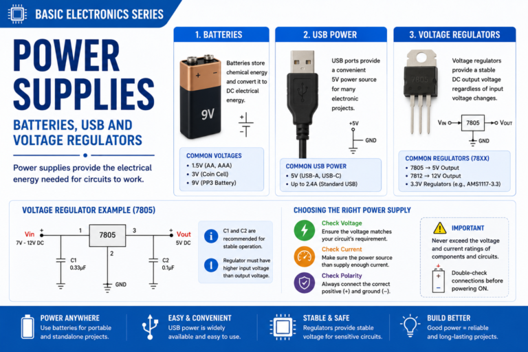
Post 12: Power Supplies — Batteries, USB, Regulators (7805, LM317, AMS1117)
Powering your circuits correctly is as important as the circuit itself — linear regulators, switching supplies, and choosing the right power source.