The component that stores energy, filters noise, and keeps your circuits stable
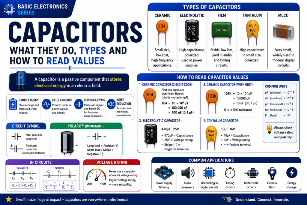
Table of Contents
Introduction
Every power supply, microcontroller board, amplifier, and virtually every electronics design includes capacitors. They do things resistors cannot: store energy, block DC while passing AC, smooth voltage ripple, and decouple power supplies from noise. This post gives you the complete picture: what a capacitor is, the physics of how it works, common types, reading values, and the four main real-circuit uses.
Before learning resistors, read:
• Voltage, Current and Resistance
• Resistors color coding and types
Part 1: What is a Capacitor?
A capacitor is two conductive plates separated by an insulating dielectric. Apply voltage across the plates and positive charge builds on one plate, negative on the other — the capacitor stores this charge. It stores energy in the electric field between its plates and can release it much faster than a battery, which is why capacitors are used for power backup and energy bursts.
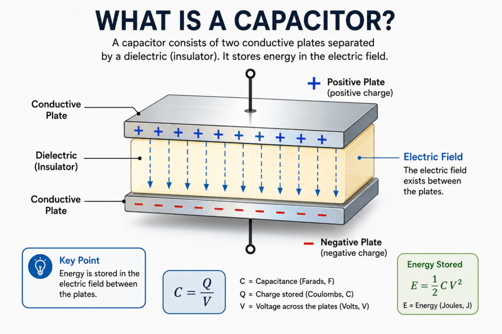
Figure 1 — Two conductive plates separated by a dielectric (insulator).
Capacitance (C) measures how much charge a capacitor stores per volt applied, in Farads (F). One Farad is enormous — most capacitors are in the microfarad (µF, 10⁻⁶F), nanofarad (nF, 10⁻⁹F), or picofarad (pF, 10⁻¹²F) range.
| Unit | Symbol | Value | Typical use |
| Picofarad | pF | 0.000000000001F | Radio frequency circuits, oscillators |
| Nanofarad | nF | 0.000000001F | Timing circuits, filters |
| Microfarad | µF | 0.000001F | Audio, power supply filtering |
| Millifarad | mF | 0.001F | Large filter caps, audio |
| Farad | F | 1F | Supercapacitors for energy storage |
Part 2: How Capacitors Behave
Connect a capacitor to a voltage source and it charges — not instantly, but following an exponential curve. The RC time constant (τ = R × C) tells you how long it takes. After one time constant, the capacitor is charged to 63% of supply voltage. After five, it’s effectively fully charged (99.3%).
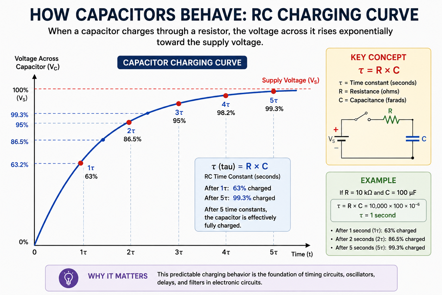
Figure 2 — RC charging curve: percent charged vs time in multiples of τ.
🔑 KEY CONCEPT
τ (tau) = R × C — the RC time constant.
After 1τ: 63% charged. After 5τ: fully charged.
Example: 10kΩ × 100µF = 1 second time constant. After 5 seconds, fully charged to supply voltage.
Capacitors block DC, pass AC — one of the most important behaviours. Once fully charged with DC, no more current flows; the capacitor looks like an open circuit to DC. For AC signals that keep changing, the capacitor constantly charges and discharges, so current keeps flowing. The higher the frequency, the easier it flows. This is capacitive reactance: Xc = 1 ÷ (2π × f × C) — higher frequency or larger capacitance means lower reactance, easier for AC to pass.
Part 3: Types of Capacitors
| Type | Polarity | Range | Key Feature | Common Uses |
| Electrolytic (aluminium) | Polarised (+/−) | 1µF – 10,000µF | Large capacitance, cheap | Power supply filtering, audio |
| Tantalum | Polarised | 0.1µF – 100µF | Stable, small size | Decoupling, portable devices |
| Ceramic (MLCC) | Non-polarised | 1pF – 100µF | Cheap, stable, small | Decoupling, RF, most common SMD |
| Film (polyester, polypropylene) | Non-polarised | 1nF – 10µF | Very stable, low noise | Audio, precision timing |
| Mica | Non-polarised | 1pF – 10nF | Very precise, stable | RF circuits, precision filters |
| Supercapacitor | Polarised | 0.1F – 10,000F | Huge capacitance | Energy storage, backup power |
⚠️ WARNING
Electrolytic and tantalum capacitors are POLARISED — they have a + and − leg.
Connect them backwards and they can leak, swell, or EXPLODE.
The negative leg of an electrolytic is marked with a − stripe and is shorter.
Always check polarity before powering up a circuit with electrolytic capacitors.
Part 4: Reading Capacitor Values
Electrolytic capacitors are large enough to print the value directly: ‘100µF 25V’ means 100 microfarads, rated up to 25 volts. The voltage rating must exceed the circuit voltage by at least 20% margin — use a 25V cap on a 12V line, not a 16V cap.
Ceramic and small capacitors use a 3-digit code just like resistors: first two digits are the value, third is the multiplier, result in picofarads (pF).
| Code | Calculation | Value |
| 104 | 10 × 10⁴ pF | 100,000pF = 100nF = 0.1µF (very common decoupling value!) |
| 103 | 10 × 10³ pF | 10,000pF = 10nF |
| 472 | 47 × 10² pF | 4,700pF = 4.7nF |
| 220 | 22 × 10⁰ pF | 22pF |
| 101 | 10 × 10¹ pF | 100pF |
💡 TIP
The 100nF (0.1µF) ceramic capacitor coded ‘104’ is the most important capacitor in electronics.
You’ll use it on every single microcontroller power pin as a decoupling capacitor.
Buy 100 of them (they cost almost nothing) and put them near every IC’s VCC pin.
Part 5: Four Main Uses in Real Circuits
Use 1: Decoupling / Bypass
Place a 100nF ceramic capacitor between VCC and GND, physically as close as possible to each IC’s power pin. When the IC switches rapidly, it draws sudden current spikes; the capacitor provides this charge locally, preventing voltage dips and noise on the power rail. Rule: 100nF ceramic on EVERY IC power pin, always. Add a 10µF electrolytic nearby for lower-frequency filtering.
Use 2: Power Supply Smoothing
After a rectifier (which converts AC to pulsating DC), a large electrolytic capacitor (typically 1000µF – 10,000µF) smooths the pulsating DC into steady DC, charging on each pulse and filling in the gaps.
Use 3: RC Timing Circuits
Pair a resistor and capacitor to create predictable time delays. The 555 timer IC uses this to create accurate oscillations, with τ = R × C determining the timing.
Use 4: Signal Coupling / Blocking DC
In audio circuits, a capacitor in series with the signal path blocks DC offsets while passing the audio AC signal — called AC coupling or DC blocking. Common values: 1µF – 10µF for audio frequencies.
✅ QUICK RECAP
A capacitor stores charge between two plates separated by a dielectric.
Capacitance unit: Farad. Common values: pF (radio), nF (timing), µF (filtering).
Electrolytic and tantalum are polarised — connect backwards and they can explode.
3-digit code on ceramics: first two digits + multiplier in pF. 104 = 100nF.
Voltage rating must exceed circuit voltage by at least 20% margin.
Four main uses: decoupling, power smoothing, RC timing, AC coupling.
100nF ceramic capacitor on every IC power pin — always, no exceptions.
Frequently Asked Questions
Q: Why do I need both a 100nF and a 10µF capacitor near the same IC?
A: They filter different frequency ranges. The small 100nF ceramic responds fast enough to squash brief, high-frequency current spikes right at the pin, while the larger 10µF electrolytic handles slower, lower-frequency dips in the supply rail.
Q: What happens if I use a capacitor with too low a voltage rating?
A: The dielectric between the plates can break down under the excess voltage, causing the capacitor to short, leak, or in the case of electrolytics, swell and potentially vent or rupture. Always leave at least 20% headroom.
Q: How is a capacitor different from a battery?
A: Both store energy, but a battery stores it chemically and releases it slowly over a long time at a fairly constant voltage. A capacitor stores energy in an electric field and can charge or discharge far faster, but its voltage drops as it discharges and its total energy storage is much lower per unit size.
Q: Why do ceramic capacitors not need polarity but electrolytics do?
A: Ceramic capacitors use a symmetric dielectric structure with no inherent directionality. Electrolytic capacitors form their dielectric layer electrochemically during manufacture, which only works correctly with voltage applied in one direction — reversing it breaks down that layer.
Q: What is ESR and why does it matter for electrolytic capacitors?
A: ESR (Equivalent Series Resistance) is the small internal resistance a capacitor has, which causes it to heat up under ripple current and limits how well it filters at higher frequencies. Low-ESR capacitors are preferred in switching power supplies for this reason.
Q: Can I substitute a larger capacitance value than specified in a circuit?
A: Sometimes, but not always safely. For general decoupling, a larger value is usually fine or even better. For RC timing circuits, however, changing the capacitance directly changes the timing (τ = R×C), so substituting will change the circuit’s behaviour.
🚀 NEXT UP
Post 7: Diodes — What They Are, How They Work, and Real Uses
Diodes are the first semiconductor component — letting current flow only one way, enabling rectifiers, clamps, protection circuits, and LEDs.