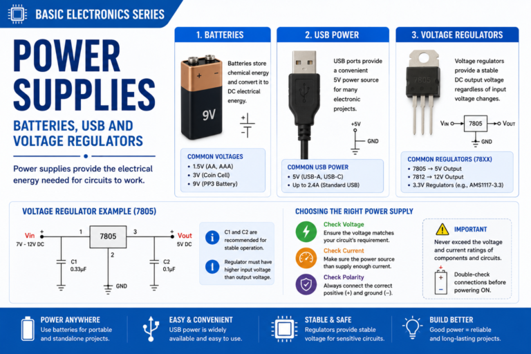
V = IR. Two letters and an equals sign. The most powerful formula in all of electronics.
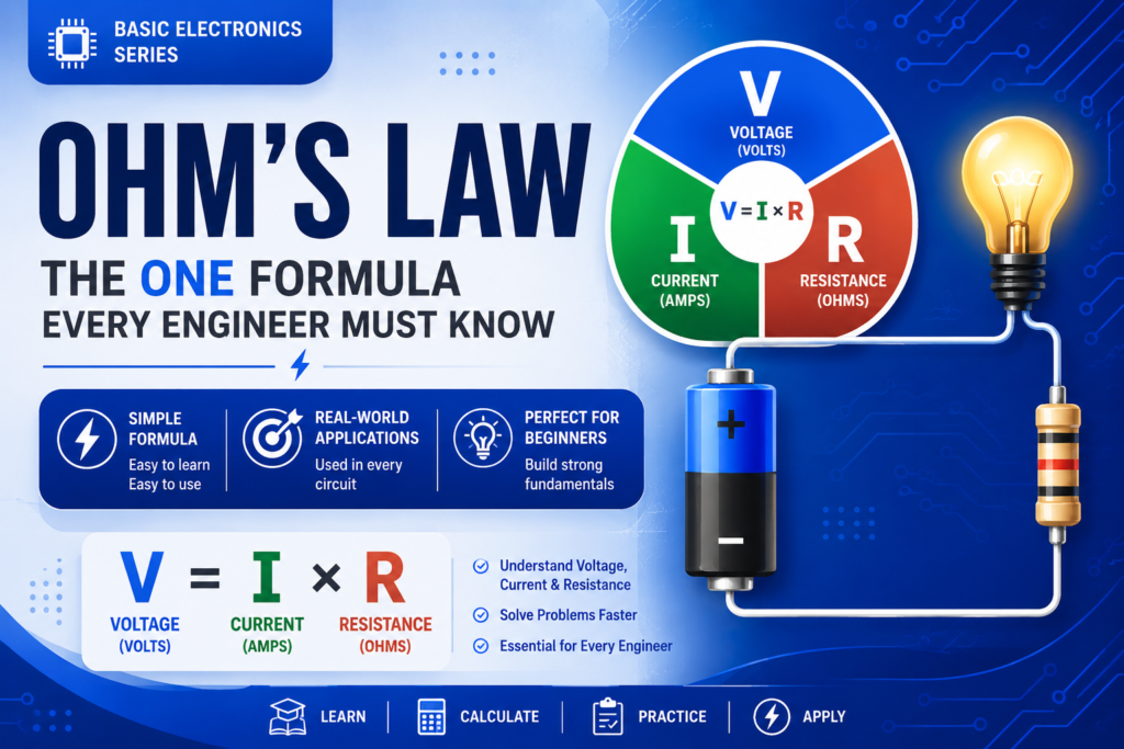
Table of Contents
Introduction
In Post 1 we understood what voltage, current, and resistance are. Now we put them together. Ohm’s Law is the relationship connecting all three, and it’s the single most used formula in electronics — from calculating a resistor value for an LED to designing power supply circuits.
The formula looks deceptively simple: V = I × R. Understanding how to use it in all three forms, apply it to real circuits, and think in Ohm’s Law is what separates someone who reads circuits from someone who designs them.
📝 NOTE
This post has maths, but only multiplication and division.
Every calculation is explained step by step with a real example.
Work through each example with a calculator alongside.
Part 1: The Formula
Georg Simon Ohm discovered in 1827 that current through a conductor is directly proportional to the voltage across it, as long as temperature stays constant. He expressed this as V = I × R (Voltage = Current × Resistance).
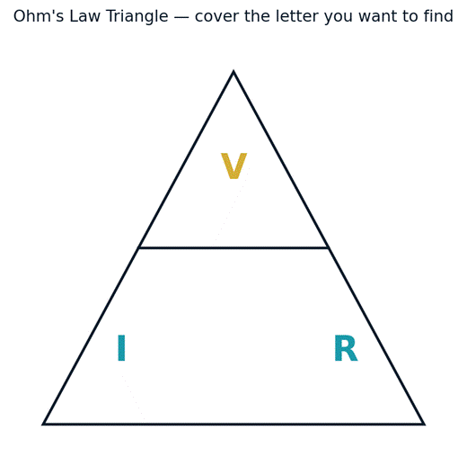
Figure 1 — The Ohm’s Law triangle. Cover the letter you want to find; the remaining two show the formula.
| What you want to find | Formula | When to use it |
| Voltage (V) | V = I × R | You know current and resistance |
| Current (I) | I = V ÷ R | You know voltage and resistance |
| Resistance (R) | R = V ÷ I | You know voltage and current |
Part 2: Real Calculations — Step by Step
Example 1: LED Resistor Calculation
Problem: connect a red LED to an Arduino 5V pin. The LED needs 20mA (0.02A) and has a forward voltage of 2V. What resistor do you need?
1. Find the voltage across the resistor: V_R = Supply − LED voltage = 5 − 2 = 3V
2. Use Ohm’s Law: R = V ÷ I = 3 ÷ 0.02 = 150Ω
3. Choose nearest standard resistor: 150Ω or 220Ω (220Ω is slightly safer — less current)
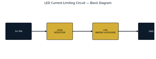
Figure 2 — The LED current-limiting circuit as a block diagram.
⚡ REAL WORLD
Standard resistor values follow the E12 or E24 series.
Common values near 150Ω: 120Ω, 150Ω, 180Ω, 220Ω.
Always go slightly higher (more resistance) to be safer with LEDs.
Example 2: How Much Current Flows?
A 9V battery is connected to a 470Ω resistor. I = V ÷ R = 9 ÷ 470 = 0.01915A = 19.15mA — enough to light an LED near-full brightness.
Example 3: What Voltage Drop Across a Resistor?
50mA (0.05A) flows through a 100Ω resistor. V = I × R = 0.05 × 100 = 5V. If powered by a 5V supply, ALL the voltage is dropped here — nothing left for other components.
Example 4: Measuring an Unknown Resistance
5V is applied across an unknown resistor and 12.5mA (0.0125A) flows. R = V ÷ I = 5 ÷ 0.0125 = 400Ω.
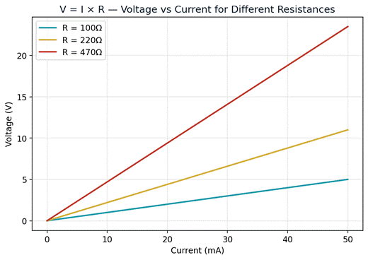
Figure 3 — V vs I for three different resistances. Steeper line = higher resistance, since V = I×R.
🛠️ TRY IT
Build this on a breadboard: 9V battery → 470Ω resistor → LED → GND.
Use a multimeter to measure voltage across the resistor and current through the circuit.
Verify: V_resistor ÷ I should equal 470Ω. You’ve experimentally verified Ohm’s Law!
Part 3: Power — The Fourth Element
Power tells you how much energy is consumed or generated per second, measured in Watts (W): P = V × I. Every component has a power rating — the maximum power it can handle before overheating and failing.
| Component | Typical Power Rating | What happens if exceeded |
| ¼W resistor | 0.25 Watts | Gets very hot, smoke, burns, opens circuit |
| 1W resistor | 1 Watt | Same, but higher tolerance |
| Small LED | ~30-80 mW | Burns out the LED junction |
| Voltage regulator (7805) | 1W (up to 15W with heatsink) | Thermal shutdown, then failure |
Example: a 220Ω resistor in your LED circuit carries 13.6mA. P = V × I = 3V × 0.0136A = 0.041W = 41mW — well within the 250mW rating of a standard ¼W resistor, safe to use.
⚠️ WARNING
Always check the power rating of your resistors.
If power > 250mW, use a ½W or 1W resistor instead of the standard ¼W.
A hot resistor is working at its limit — reduce current or use a higher rating.
Part 4: Kirchhoff’s Laws — The Next Step
Ohm’s Law describes the relationship within a single component. Kirchhoff’s Laws extend this to entire circuits with multiple components, and you’ll use these constantly when analysing real circuits.
Kirchhoff’s Current Law (KCL)
The total current entering any junction equals the total current leaving it. Charge cannot be created or destroyed — it must all go somewhere.
🔑 KEY CONCEPT
If 100mA flows into a junction that splits into two wires, one might carry 60mA and the other 40mA. 60 + 40 = 100. Always.
Kirchhoff’s Voltage Law (KVL)
The sum of all voltage drops around any closed loop equals zero. In simpler terms: the voltages across all components in a series circuit must add up to the supply voltage.
🔑 KEY CONCEPT
9V battery → 330Ω resistor (3.3V drop) → LED (2V drop) → 470Ω resistor (3.7V drop) → GND.
3.3 + 2 + 3.7 = 9V. The drops add up to the supply. Always.
✅ QUICK RECAP
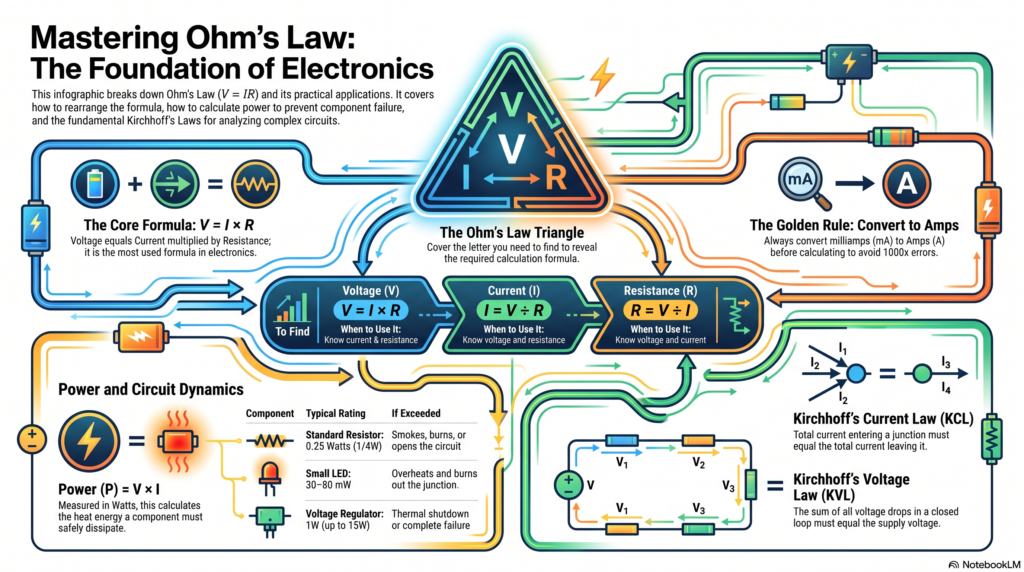
V = I × R — Ohm’s Law, the most used formula in electronics.
Three forms: V = IR, I = V/R, R = V/I.
P = V × I — Power in Watts. Never exceed component power ratings.
KCL: current into a junction = current out. Charge is conserved.
KVL: voltage drops around a loop sum to zero.
Always convert milliamps to amps (÷1000) before using Ohm’s Law.
Frequently Asked Questions
Q: Does Ohm’s Law apply to every component?
A: It applies precisely to ‘ohmic’ components like standard resistors, where resistance stays constant regardless of voltage. Diodes, LEDs, and transistors are non-ohmic — their resistance changes with the operating point, so Ohm’s Law is used locally (e.g. for the resistor in an LED circuit) rather than across the whole nonlinear device.
Q: Why do I need to convert mA to A before calculating?
A: Ohm’s Law works in base SI units — volts, amps, ohms. If you plug in 20 (meaning 20mA) instead of 0.02 (20mA in amps), your resistance answer will be off by a factor of 1000. Always convert first.
Q: What happens if I use a resistor value lower than calculated?
A: Lower resistance means more current flows (I = V/R). For an LED this risks exceeding its maximum current rating, causing it to overheat and fail — often within seconds.
Q: Why do we round to the ‘nearest standard value’ instead of the exact calculated resistance?
A: Resistors are manufactured only in standard series (E12, E24, etc.) — see Post 5. You pick the nearest available value, usually rounding up slightly for safety-critical current limiting.
Q: How is power rating different from voltage rating?
A: Power rating (Watts) is how much heat a component can dissipate before damage. Voltage rating is the maximum voltage a component (like a capacitor) can withstand before its insulation breaks down. They protect against different failure modes.
Q: What’s a quick way to remember Kirchhoff’s two laws?
A: KCL is about junctions and current: ‘what goes in must come out.’ KVL is about loops and voltage: ‘all the drops must add back up to the supply.’ Current law = nodes, voltage law = loops.
🚀 NEXT UP
Post 3: Series vs Parallel Circuits — With Real Examples
You’ll learn how voltage and current behave differently when components are connected in series vs parallel — and how to analyse both.