POST 12 ● SERIES 1: ELECTRONICS BASICS ● 13 min read
Get the power right first — everything else depends on a stable, clean supply
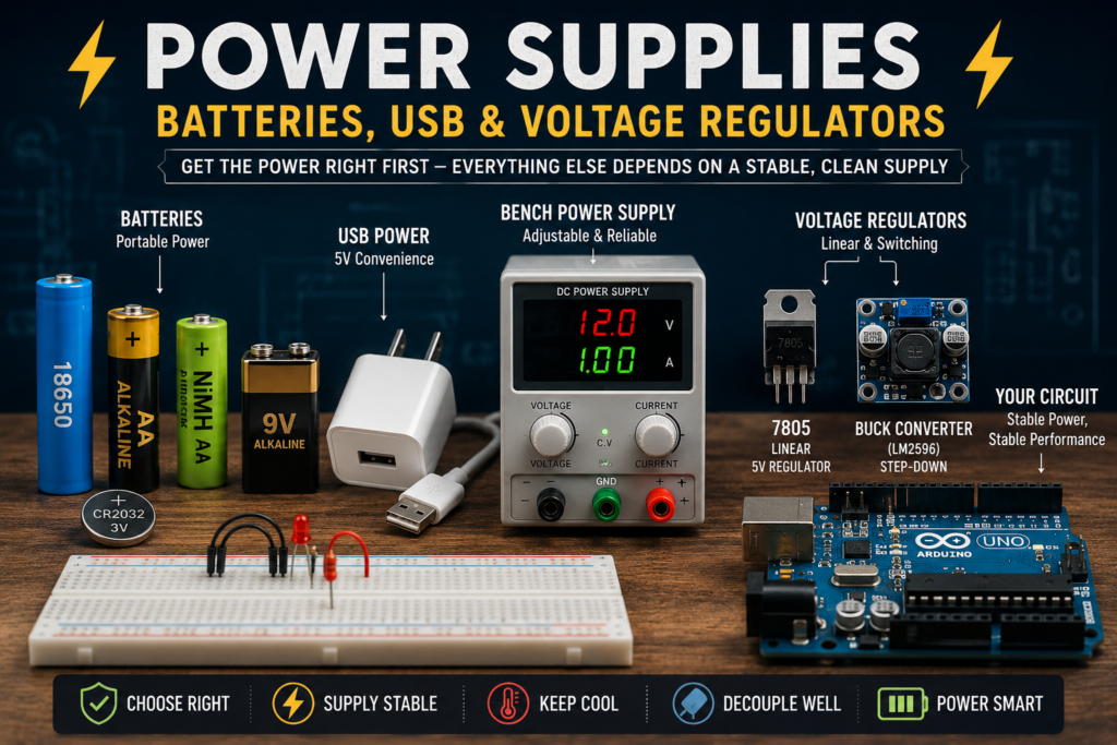
Table of Contents
Introduction
The power supply is the foundation of every electronic circuit. Get it wrong and nothing works correctly — your MCU resets randomly, sensors give wrong readings, motors behave erratically. This post covers every common power source: batteries, USB, wall adapters, and voltage regulators — linear (7805, LM317, AMS1117) and switching — and how to choose the right power supply for any project.
Part 1: Batteries
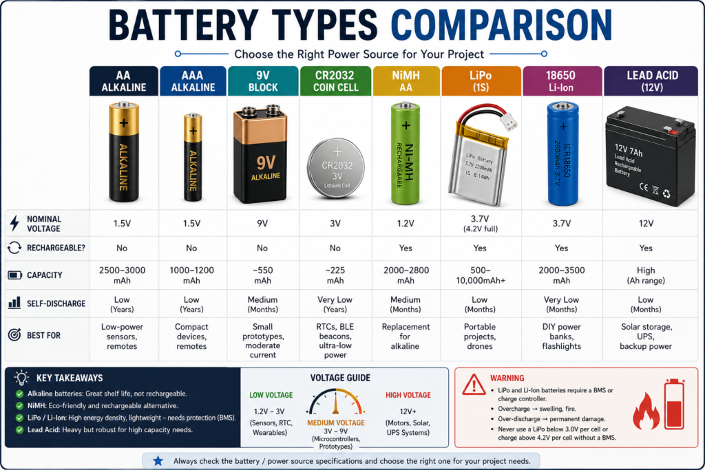
| Battery Type | Voltage | Rechargeable? | Capacity | Self-discharge | Best for |
| AA Alkaline | 1.5V | No | 2500-3000mAh | Low (years) | Low-power sensors, remotes |
| AAA Alkaline | 1.5V | No | 1000-1200mAh | Low | Compact devices, remotes |
| 9V Block | 9V | No | 550mAh | Medium | Small prototypes, moderate current |
| CR2032 Coin | 3V | No | 225mAh | Very low | RTCs, BLE beacons, ultra-low power |
| NiMH AA | 1.2V | Yes | 2000-2800mAh | Medium | Replacement for alkaline |
| LiPo (1S) | 3.7V nominal, 4.2V full, 3.0V min | Yes | 500-10,000mAh+ | Low | Portable projects, drones |
| 18650 Li-Ion | 3.7V | Yes | 2000-3500mAh | Very low | DIY power banks, flashlights |
| Lead Acid | 12V | Yes | High (Ah) | Low | Solar storage, UPS, backup |
⚠️ WARNING
LiPo and Li-Ion batteries require a Battery Management System (BMS) or charge controller.
Overcharge → swelling, fire. Over-discharge → permanent damage.
Never use a LiPo below 3.0V per cell or charge above 4.2V per cell without a BMS.
Part 2: USB Power
USB is the most convenient power source for prototyping. Understanding the different standards prevents common power problems.
| USB Standard | Voltage | Current available | Wattage | Notes |
| USB 2.0 | 5V | 500mA = 0.5A | 2.5W | Standard PC port. Enough for Arduino Uno + a few sensors. |
| USB 3.0 | 5V | 900mA = 0.9A | 4.5W | Slightly more current available. |
| USB Charging Port | 5V | 1.5-2.4A | 7.5-12W | Charger ports. Good for Raspberry Pi 3. |
| USB-C (5V mode) | 5V | up to 3A | 15W | Most modern chargers. Raspberry Pi 4. |
| USB PD | 5-20V | up to 5A | 100W | Negotiated voltage. Powers anything. |
💡 TIP
Raspberry Pi 4 needs a genuine USB-C 5V 3A charger.
Using an old phone charger (5V 1A) will cause throttling and SD card corruption.
Always check the power supply rating before connecting. The RPi OS shows a lightning bolt icon in the corner when under-voltage is detected.
Part 3: Linear Voltage Regulators
A linear regulator takes a higher input voltage and converts it to a stable, lower output voltage — the excess is dissipated as heat. They’re simple and low-noise, but inefficient, especially when the input is much higher than the output.
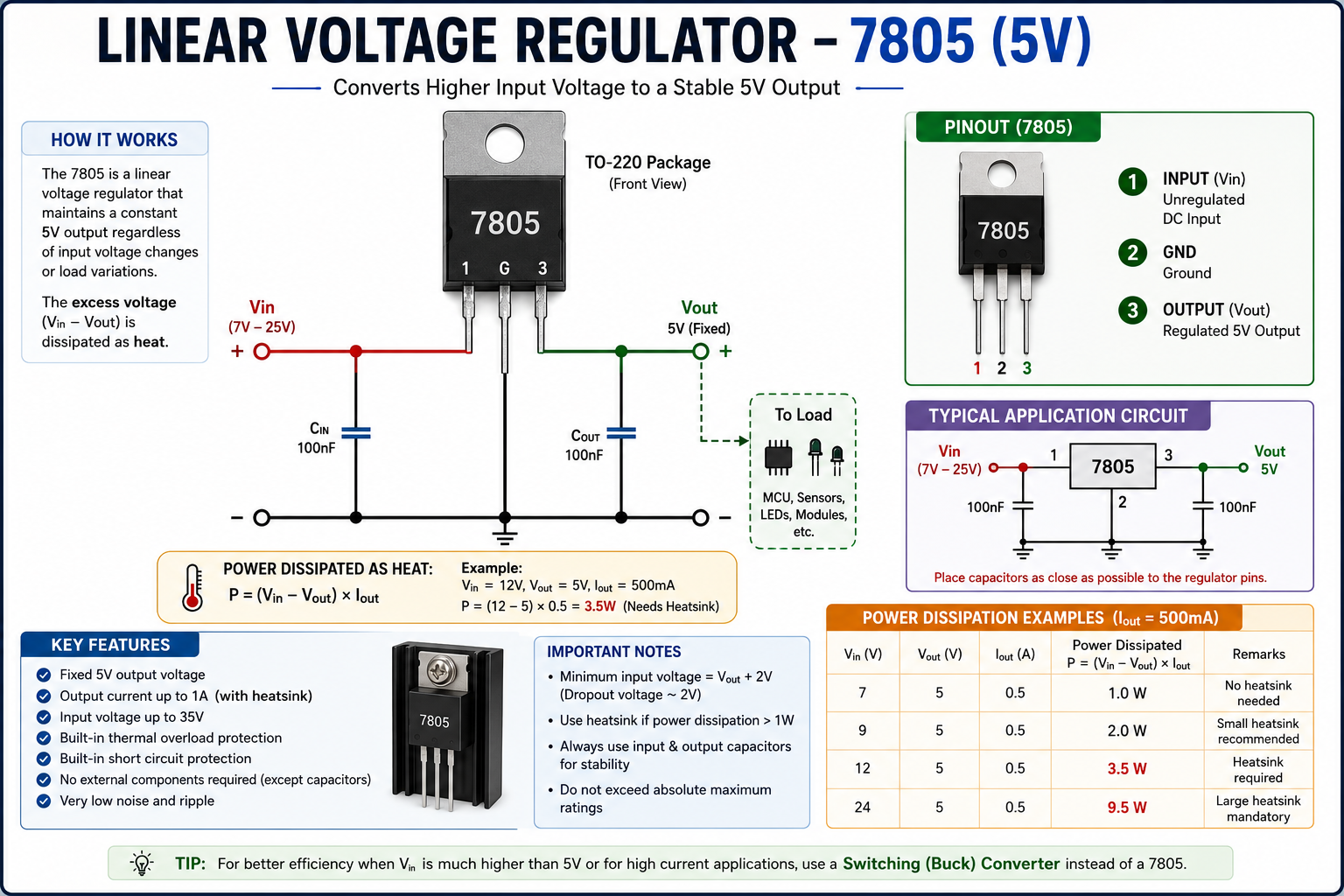
Figure 1 — Linear regulator block diagram: excess voltage becomes heat.
7805 — The Classic 5V Regulator
A three-pin TO-220 package regulator: Input, GND, Output. Fixed 5V output, up to 1A (with heatsink). Needs input of at least 7V (dropout ~2V). Add 100nF on input and 100nF on output. Power dissipated as heat: P = (Vin − Vout) × Iout. Example: Vin=12V, Vout=5V, Iout=500mA → P = (12−5) × 0.5 = 3.5W — very hot, needs a heatsink.
LM317 — Adjustable Regulator
Outputs any voltage from 1.25V to 37V using two resistors: Vout = 1.25 × (1 + R2/R1). Maximum output current: 1.5A. Three pins: Input, Adjust, Output. Set R1 = 240Ω (fixed), then calculate R2 for desired output. Example for 5V: R2 = 240 × (5/1.25 − 1) = 720Ω — use 680Ω + 100Ω trim pot for precision.
AMS1117 — The MCU Favourite
A low-dropout (LDO) regulator in SOT-223 or TO-252 package. Available in fixed 3.3V, 5V, 1.8V versions. Used on virtually every Arduino, Raspberry Pi, and ESP32 board to generate 3.3V from 5V. Low dropout: only 1.1-1.3V needed above output, up to 1A.
| Regulator | Output | Max Current | Dropout voltage | Package | Best for |
| 7805 | 5V fixed | 1A (with heatsink) | ~2V | TO-220 | General 5V from 9-12V |
| 7809/12 | 9V, 12V | 1A | ~2V | TO-220 | Fixed voltage applications |
| LM317 | 1.25-37V adj | 1.5A | ~2V | TO-220 | Adjustable bench supply |
| AMS1117-3.3 | 3.3V fixed | 1A | 1.1V | SOT-223, TO-252 | MCU 3.3V rail from 5V |
| LD1117 | 3.3V, 5V fixed | 0.8A | 1.1V | TO-220, SOT-223 | Similar to AMS1117 |
| MCP1700 | 1.8-5V fixed | 250mA | 0.18V | SOT-23 | Ultra-low power IoT nodes |
Part 4: Switching Regulators
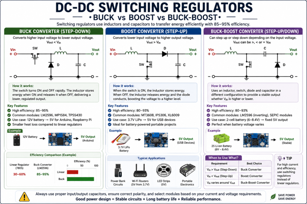
Switching regulators (SMPS) use an inductor and capacitor to store and transfer energy efficiently. Instead of wasting excess voltage as heat, they switch rapidly and convert voltage with 85-95% efficiency.
Buck Converter (Step-Down)
Converts higher input voltage to lower output, ~85-95% efficient. Common modules: LM2596 (up to 3A), MP1584 (up to 3A, very small), TPS5430 (integrated IC). Use case: 12V battery → 5V for Arduino. A 7805 would waste (12-5)×0.5A = 3.5W as heat; a buck converter wastes only ~0.25W.
Boost Converter (Step-Up)
Converts lower voltage to higher output. Example: 3.7V LiPo → 5V for USB. Common: MT3608, IP5306.
Buck-Boost
Can step up or step down — used when battery voltage changes but output must stay constant (e.g. 2-cell battery 6-8.4V → fixed 5V output).
Figure 3 — Typical efficiency ranges by regulator type.
| Type | Efficiency | Noise | Complexity | Cost | Use when |
| Linear (7805, LM317) | 30-60% | Very low (good) | Low | Very cheap | Small current, quiet needed (audio/RF) |
| LDO (AMS1117) | 60-85% | Low | Low | Cheap | Small voltage difference, moderate current |
| Buck SMPS | 85-95% | Medium (needs filtering) | Medium | Moderate | Efficient step-down, high current |
| Boost SMPS | 80-93% | Medium | Medium | Moderate | Step-up needed |
Part 5: Designing Your Power Supply
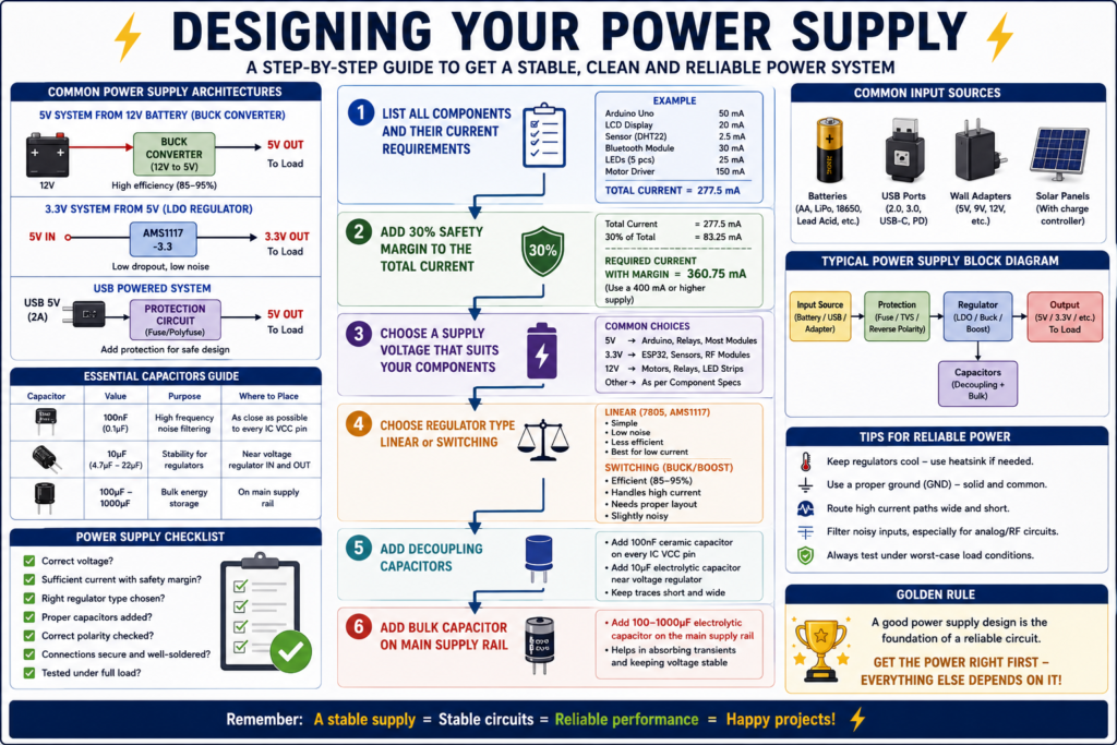
1. List all components and their current requirements. Sum them all.
2. Add 30% safety margin to the total current.
3. Choose a supply voltage that suits your components (usually 5V or 3.3V).
4. Choose regulator type: linear (simple, clean, low current) vs switching (efficient, high current).
5. Add decoupling capacitors: 100nF ceramic on every IC VCC pin, 10µF electrolytic nearby.
6. Add a bulk capacitor (100-1000µF) on the main supply rail.
✅ QUICK RECAP
LiPo/Li-Ion: 3.7V nominal, needs BMS. Never below 3.0V per cell.
USB 2.0: 5V 500mA. USB-C PD: 5-20V up to 100W.
7805: fixed 5V, TO-220, needs heatsink if high current.
AMS1117-3.3: LDO, used on virtually every MCU board for 3.3V rail.
LM317: adjustable 1.25-37V. Formula: Vout = 1.25 × (1 + R2/R1).
Buck converter: efficient step-down. 85-95% vs 30-60% for linear.
Always add 100nF decoupling cap on every IC power pin.
Frequently Asked Questions
Q: Should I choose a linear regulator or a switching regulator for my project?
A: Use a linear regulator (7805, AMS1117) when the voltage drop is small and current needs are modest — they’re simpler and quieter. Use a switching regulator (buck/boost module) when the voltage drop is large or current needs are high, since it wastes far less energy as heat.
Q: Why does my 7805 get so hot even at moderate current?
A: Linear regulators dissipate the voltage difference times the current as heat: P = (Vin − Vout) × Iout. A large gap between input and output voltage, combined with a few hundred milliamps of load, quickly adds up to several watts that must be removed with a heatsink.
Q: Can I power a 5V Arduino directly from a 3.7V LiPo battery?
A: Not directly — 3.7V is below the Arduino’s minimum input requirement in most cases. You’d need a boost converter to step 3.7V up to a stable 5V, or use a board specifically designed for direct LiPo input.
Q: Is it safe to use a higher-current power supply than my device needs?
A: Yes — the device only draws the current it needs; a supply rated for more current than required simply has extra headroom and won’t force more current into the circuit. What matters is that the voltage and polarity match.
Q: Why do I need a BMS for LiPo batteries but not for alkaline?
A: LiPo cells can be permanently damaged, swell, or catch fire if overcharged, over-discharged, or short-circuited, because the chemistry is far less forgiving than the reactions in a simple alkaline cell. A BMS actively protects against these failure modes.
Q: What’s the simplest way to check if my power supply is adequate for a Raspberry Pi?
A: Use a genuine, correctly rated USB-C 5V 3A supply for a Pi 4 (or the appropriate rating for your model), and watch for the under-voltage warning icon in the Raspberry Pi OS — its appearance is a clear, built-in signal that the supply isn’t delivering enough current.
🚀 NEXT UP
Post 13: What is a PCB? From Breadboard to Printed Circuit
The final post covers how real circuits are manufactured on PCBs — layers, materials, reading a PCB, and the path from prototype to product.