Control a 10A motor from a 5mA Arduino pin — this is what transistors do
Table of Contents
Introduction
Your Arduino GPIO pin can source or sink about 40mA maximum. A small DC motor might need 500mA. A relay coil needs 100mA. A string of LEDs might need 2A. How do you control these high-power loads from a tiny microcontroller pin? Transistors.
A transistor uses a small input signal to control a much larger output current. In switch applications, a tiny base/gate current switches on or off a large collector/drain current. There are two main types used in switching applications: the BJT and the MOSFET. This post explains both with complete circuits you can build today.
Part 1: BJT — Bipolar Junction Transistor
A BJT has three terminals: Base, Collector, Emitter, and two polarities: NPN (most common) and PNP. In an NPN transistor used as a switch: a small current into the BASE turns it ON; when ON, current flows from COLLECTOR to EMITTER; when OFF (no base current), no collector current flows.
🔑 KEY CONCEPT
BJT is a current-controlled device: a small BASE current controls a large COLLECTOR current.
Current gain (hFE or β): Ic = hFE × Ib. Typical hFE = 100-500.
Supply 1mA to the base with hFE = 200, and the collector can carry up to 200mA.
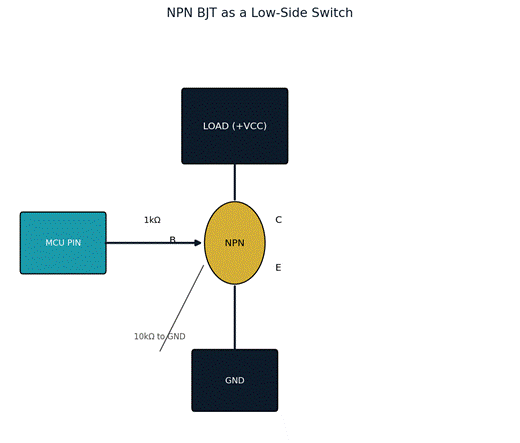
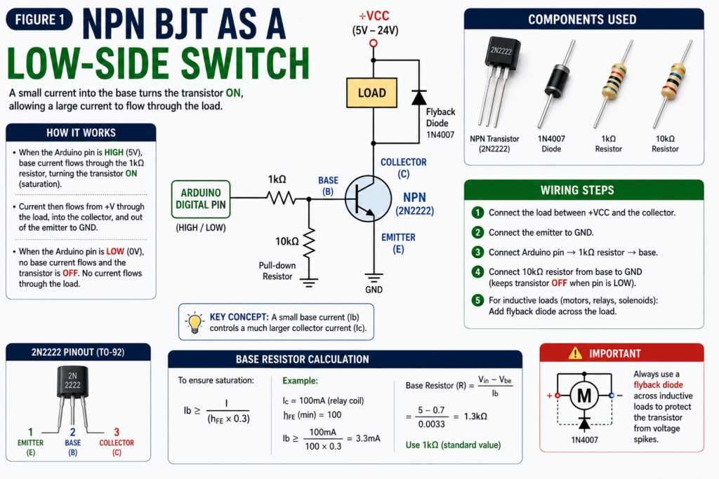
Figure 1 — NPN BJT wired as a low-side switch, with base and pull-down resistors.
NPN Transistor Switch Circuit
1. Connect load between positive supply and collector
2. Connect emitter to GND
3. Connect Arduino pin → 1kΩ resistor → base
4. Connect 10kΩ resistor from base to GND (ensures transistor is fully off when pin is LOW)
5. For inductive loads (motors, relays): add flyback diode across the load
Calculating the Base Resistor
To fully saturate the transistor, base current must be enough: Ib ≥ Ic ÷ (hFE × 0.3). The 0.3 factor ensures we overdrive the base for reliable saturation.
Example: switching a relay that draws 100mA (Ic), using 2N2222 (hFE min = 100). Required Ib ≥ 100mA ÷ (100 × 0.3) = 3.3mA. Base resistor: R = (Vin − Vbe) ÷ Ib = (5 − 0.7) ÷ 0.0033 = 1300Ω, use 1kΩ (gives more base current = safer saturation).
| BJT Type | Common Part | Max Ic | Max Vce | Use Case |
| NPN small signal | 2N2222, BC547 | 600mA, 800mA | 30V, 45V | Switching LEDs, small relays, buzzers |
| NPN medium power | TIP31, TIP120 | 3A, 5A | 60V, 60V | Motors, larger relays, heaters |
| NPN power | TIP35, 2N3055 | 25A, 15A | 100V, 115V | High power loads |
| PNP small signal | 2N2907, BC557 | 600mA, 100mA | 40V, 45V | High-side switching |
| Darlington pair | TIP120, ULN2003 | 5A (per channel) | 60V | Direct GPIO to motor (built-in resistor) |
Part 2: MOSFET — Metal Oxide Semiconductor FET
MOSFETs have virtually replaced BJTs in most switching applications because: they’re voltage-controlled — the gate draws almost zero current; they have lower on-state resistance (RDS_on), wasting less power when fully on; they switch faster, better for PWM control of motors and LEDs; and they’re easy to drive from 3.3V microcontrollers using logic-level parts like the IRLZ44N.
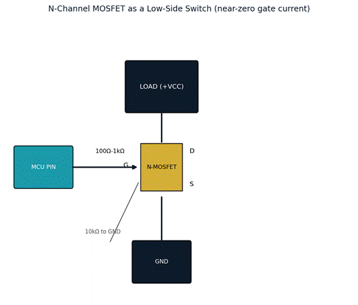
Figure 2 — N-channel MOSFET wired as a low-side switch.
N-Channel MOSFET Switch Circuit
1. Connect DRAIN to the load (between load and MOSFET)
2. Connect SOURCE to GND
3. Connect Arduino pin → GATE (often through 100Ω-1kΩ to limit gate current spikes)
4. Add 10kΩ resistor from gate to GND (ensures MOSFET is fully OFF when pin is floating or LOW)
5. Add flyback diode across inductive load
🔑 KEY CONCEPT
For N-Channel low-side switching: load between VCC and DRAIN, SOURCE to GND.
When GATE voltage exceeds VGS(th) threshold, MOSFET turns on.
Use ‘logic level’ MOSFETs (VGS(th) ~2V) for 3.3V or 5V microcontroller direct drive.
| MOSFET | Type | Vgs(th) | RDS(on) | Max Id | Use |
| 2N7000 | N-ch logic | 2.1V | 1.8Ω | 200mA | Small logic switching |
| IRLZ44N | N-ch logic | 2.0V | 0.022Ω | 47A | Motor, LED strips, high current |
| IRF520 | N-ch | 4.0V | 0.270Ω | 9.7A | 5V-compatible with pull-up |
| AO3400 | N-ch SMD | 1.6V | 0.035Ω | 5.7A | SMD low-side switch |
| STP36NF06 | N-ch | 2.5V | 0.028Ω | 30A | High current motor drivers |
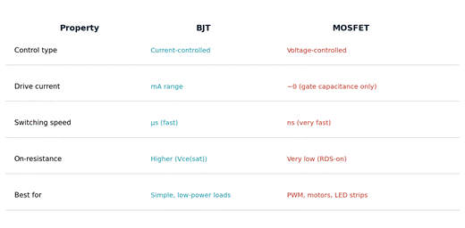

Figure 3 — BJT vs MOSFET at a glance.
Part 3: Relay vs Transistor vs MOSFET — When to Use Which
| Device | Isolation | Speed | Power needed | Handles AC? | Best for |
| Relay | Yes (coil vs contacts) | Slow (ms) | Coil current needed | Yes! | Mains switching, AC loads, complete isolation |
| BJT | No | Fast (µs) | Small base current | No | Simple low-power loads, old designs |
| MOSFET | No | Very fast (ns) | Near zero gate current | No (special circuits) | DC motor PWM, LED strips, most modern designs |
💡 TIP
For most maker projects driving DC loads: use an N-channel logic-level MOSFET (IRLZ44N).
For mains AC switching: use a relay module (never directly, always with opto-isolation).
For multiple channels: ULN2003 (Darlington array) handles 7 channels at 500mA each.
✅ QUICK RECAP
BJT: current-controlled. Small base current → large collector current. NPN most common.
MOSFET: voltage-controlled. Near-zero gate current. Much more efficient than BJT.
N-channel: load between VCC and DRAIN. SOURCE to GND. Gate controls switching.
Always add flyback diode across inductive loads (motors, relays, solenoids).
10kΩ gate-to-GND resistor keeps MOSFET OFF when control signal is disconnected.
Logic-level MOSFETs (IRLZ44N): work with 3.3V/5V GPIO directly. Use these.
Relays: for AC mains switching or when you need total isolation between circuits.
Frequently Asked Questions
Q: Why can’t I just connect a motor directly to an Arduino pin?
A: GPIO pins are limited to roughly 40mA, while even small motors typically draw hundreds of milliamps to amps. Exceeding the pin’s current limit will damage the microcontroller. A transistor or MOSFET lets the small GPIO current control a separate, much larger current path to the motor.
Q: How do I choose between a BJT and a MOSFET for a new project?
A: For most modern maker projects driving DC loads (motors, LED strips, relays) a logic-level N-channel MOSFET like the IRLZ44N is the better default — it’s more efficient, switches faster, and barely loads the GPIO pin. BJTs remain useful for very simple low-power switching or when following older reference designs.
Q: What happens if I skip the flyback diode on a relay or motor circuit?
A: The collapsing magnetic field when the inductive load switches off generates a large voltage spike, often hundreds of volts, in the opposite direction. Without a flyback diode to clamp it, that spike will usually destroy the switching transistor or MOSFET within a few cycles.
Q: Why is a 10kΩ pull-down resistor needed on the gate/base?
A: Without it, the gate or base can float to an undefined voltage when the microcontroller pin is an input, briefly high-impedance, or during power-up — potentially turning the switch partially or fully on unintentionally. The pull-down resistor guarantees a defined OFF state.
Q: Can I drive a MOSFET gate directly with no resistor at all?
A: It’s common to add a small series resistor (100Ω-1kΩ) even though the DC gate current is near zero, because the gate behaves like a small capacitor — the resistor limits the current spike when that capacitance charges and discharges during fast switching, protecting both the MCU pin and the MOSFET.
Q: What is the practical difference between a MOSFET and a relay for turning on a lamp?
A: A MOSFET switches fast and silently but only isolates in one sense (no true electrical isolation between control and load side) and generally can’t handle AC mains well. A relay provides true galvanic isolation and can switch AC mains loads, but is slower, mechanical (wears out over time), and needs more current to drive its coil.
🚀 NEXT UP
Post 10: Reading a Circuit Schematic — Symbols and Rules
Now that you know all the basic components, it’s time to read circuit diagrams — every common symbol and the rules for reading any schematic.