From a single indicator LED to RGB strips — everything you need to know about light-emitting diodes
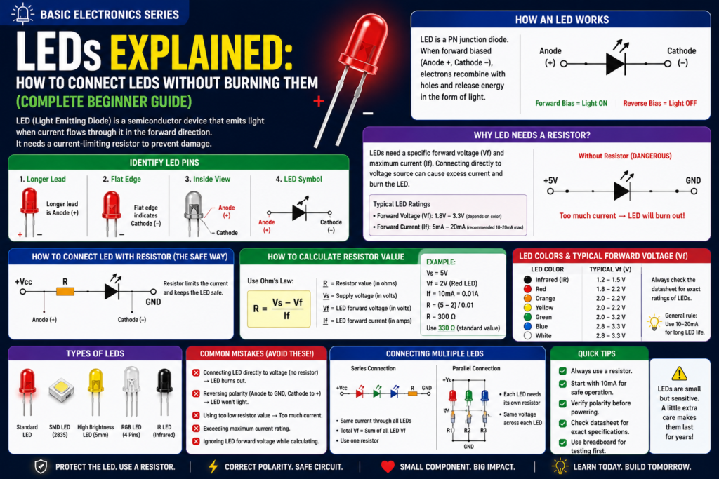
Table of Contents
Introduction
The LED is the first component most people connect to a microcontroller — and the first component most people burn out. Connecting an LED directly to 5V without a resistor destroys it in seconds. Done correctly, LEDs are incredibly versatile: indicators, displays, backlights, decorative lighting, and communication signals. This post covers physics, current calculations, LED types, RGB LEDs, PWM dimming, and addressable strips like WS2812B.
Part 1: How LEDs Work
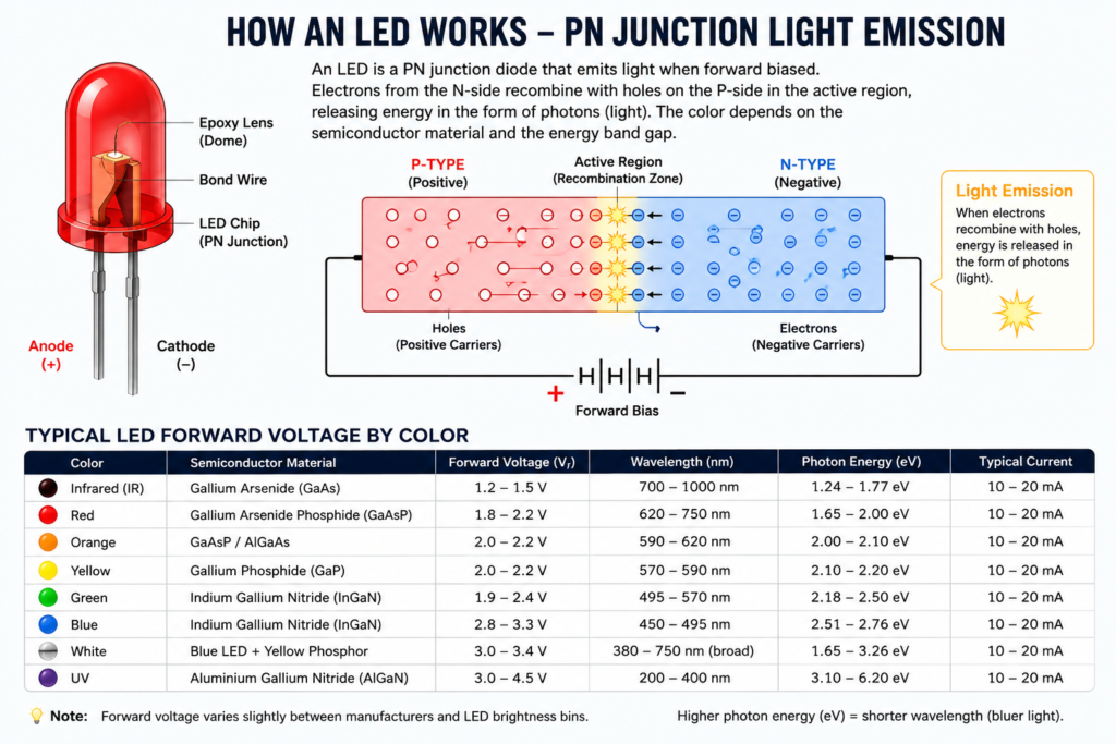
As covered in Post 7, an LED is a diode that emits light when forward biased. When electrons from the N-side recombine with holes on the P-side, they release energy as photons. The colour depends on the semiconductor material and the photon energy level.
| Colour | Semiconductor Material | Forward Voltage | Wavelength |
| Infrared (IR) | Gallium Arsenide (GaAs) | 1.2-1.5V | 700-1000nm |
| Red | Gallium Arsenide Phosphide | 1.8-2.2V | 620-750nm |
| Orange | GaAsP / AlGaAs | 2.0-2.2V | 590-620nm |
| Yellow | Gallium Phosphide (GaP) | 2.0-2.2V | 570-590nm |
| Green | Indium Gallium Nitride (InGaN) | 1.9-2.4V | 495-570nm |
| Blue | Indium Gallium Nitride | 2.8-3.3V | 450-495nm |
| White | Blue LED + Yellow phosphor | 3.0-3.4V | 380-750nm (broad) |
| UV | Aluminium Gallium Nitride | 3.0-4.5V | 200-400nm |
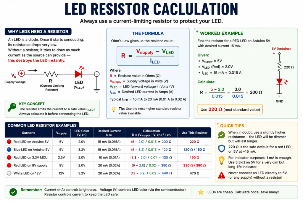
Figure 1 — Typical LED forward voltage by colour; higher-energy photons (blue/white/UV) need higher forward voltage.
Part 2: The Resistor Calculation — The Most Important Formula
An LED is a diode — once conducting, its resistance drops very low. Without a current-limiting resistor, current is limited only by wire resistance (nearly zero), and the LED pulls as much current as the source can provide. This destroys the LED in under a second.
🔑 KEY CONCEPT
R = (Vsupply − Vled) ÷ Iled
Where Vsupply = your power supply voltage, Vled = LED forward voltage, Iled = desired current (typically 10-20mA = 0.01-0.02A).
| Scenario | Vsupply | Vled | Desired Current | R calculation | Use |
| Red LED on Arduino 5V | 5V | 2.0V | 15mA (0.015A) | (5-2)/0.015 = 200Ω | 220Ω |
| Blue LED on Arduino 5V | 5V | 3.2V | 15mA | (5-3.2)/0.015 = 120Ω | 120Ω or 150Ω |
| Red LED on 3.3V MCU | 3.3V | 2.0V | 10mA (0.01A) | (3.3-2)/0.01 = 130Ω | 150Ω |
| Red LED on 9V supply | 9V | 2.0V | 20mA (0.02A) | (9-2)/0.02 = 350Ω | 330Ω or 390Ω |
| White LED on 12V | 12V | 3.2V | 20mA | (12-3.2)/0.02 = 440Ω | 470Ω |
💡 TIP
When in doubt, use a slightly higher resistance — the LED will be slightly dimmer but will last longer.
220Ω is the ‘safe default’ for a red LED on 5V — memorise this for quick breadboarding.
For indicator purposes, 1mA is plenty bright. Use 3.3kΩ on 5V for a very dim but long-life indicator.
Part 3: Identifying LED Polarity
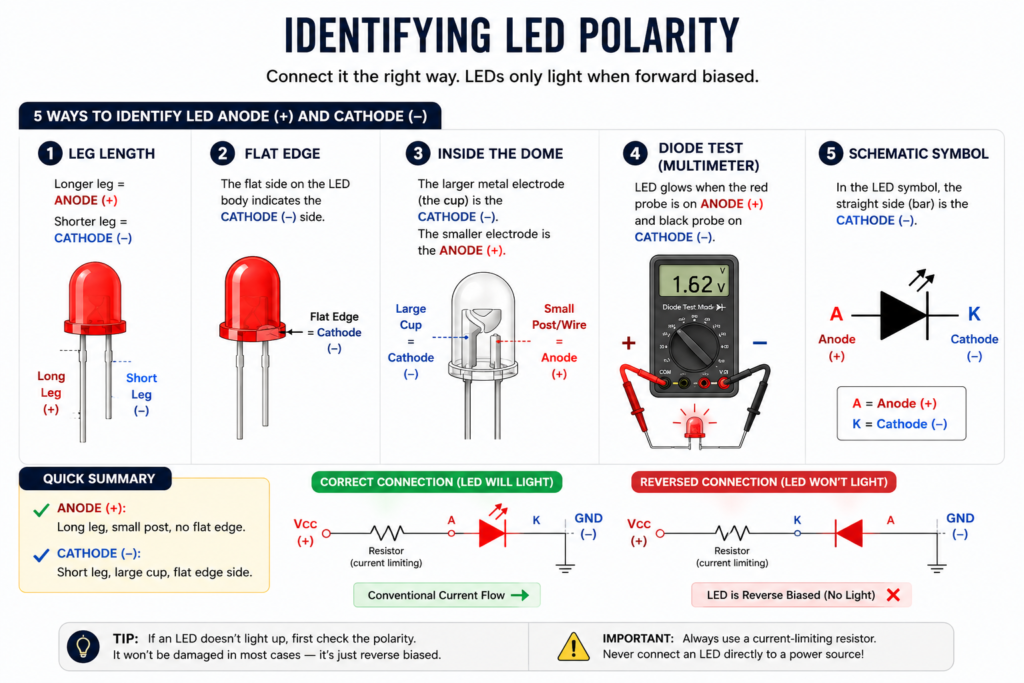
Connect an LED backwards and it won’t light (and won’t be damaged in most cases — LEDs are simply reverse-biased). How do you know which leg is which?
- Longer leg = ANODE (+) — connects toward positive voltage
- Shorter leg = CATHODE (−) — connects toward ground
- Flat edge on the LED body rim = CATHODE side
- Inside the LED dome: the larger electrode = CATHODE (the cup); the smaller wire = ANODE
- Multimeter diode test: LED glows when red probe on anode (long leg), black on cathode
Part 4: Multiple LEDs
Multiple LEDs in Parallel (Same Pin)
Each LED gets its own resistor and connects from the same pin to GND — each has full voltage and draws its own current. Total current = sum of all LED currents.
⚠️ WARNING
Arduino digital output pins can source/sink a maximum of 40mA, and the absolute maximum for ALL pins combined is 200mA.
With three LEDs at 15mA each = 45mA from one pin — this exceeds the single-pin limit.
For multiple LEDs, use a transistor or dedicated driver.
Multiple LEDs in Series
Connect LEDs end-to-end with one shared resistor — all LEDs get the same current, and voltage drops add up: R = (Vsupply − Vled1 − Vled2 − … − VledN) ÷ Iled. Example: 3 red LEDs in series on 12V: R = (12 − 2 − 2 − 2) ÷ 0.02 = 300Ω, use 330Ω. Advantage: more efficient than parallel (one resistor, lower power loss). Downside: if one LED fails open, all go dark.
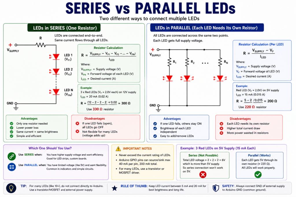
Figure 2 — LEDs in series (left, one shared resistor) vs parallel (right, each LED needs its own).
Part 5: PWM Dimming
PWM (Pulse Width Modulation) dims an LED by switching it on and off very fast (typically 490-1000 Hz). The human eye sees the average brightness — 50% on-time = 50% brightness, 10% on-time = 10% brightness. On Arduino: analogWrite(pin, value), where value is 0 (off) to 255 (full on). Works on PWM-capable pins (3, 5, 6, 9, 10, 11 on Uno).
Part 6: RGB LEDs and Addressable Strips
RGB LED (4-pin)
An RGB LED contains three separate LEDs (Red, Green, Blue) in one package with four pins: one common anode (or cathode) plus one for each colour. Mixing different intensities of R, G, B using PWM creates millions of colours.
- Common Cathode: common pin to GND, individual pins to PWM outputs via resistors
- Common Anode: common pin to VCC, individual pins LOW through resistors to GND
Addressable LED Strips (WS2812B / NeoPixel)
Each WS2812B LED contains its own control IC. A single Arduino data wire controls hundreds of individually addressable full-colour LEDs. The protocol sends 24-bit colour data (8 bits each for R, G, B) to each LED in sequence at 800kHz.
- Power: each LED draws up to 60mA at full white. 60 LEDs = 3.6A! Use a dedicated 5V supply.
- Library: Adafruit NeoPixel or FastLED — both are excellent.
- Connection: 100-500Ω resistor in series with the data line prevents ringing. 1000µF capacitor across power.
💡 TIP
Never power WS2812B strips from the Arduino 5V pin.
Use a separate 5V 2-5A power supply. Connect grounds together.
The in-rush current when all LEDs light up at full white will brown-out the Arduino.
✅ QUICK RECAP
LED is a diode that emits light when forward biased. ALWAYS use a current-limiting resistor.
Formula: R = (Vsupply − Vled) ÷ Iled. Typical: 220Ω for red LED on 5V at 15mA.
Long leg = anode (+). Short leg = cathode (−). Flat rim side = cathode.
Parallel LEDs: each needs its own resistor. Series LEDs: one resistor, voltages add up.
PWM dimming: analogWrite(pin, 0-255). Works only on PWM-capable pins.
RGB LEDs mix R+G+B to make any colour. WS2812B = individually addressable, needs 5V external supply.
Common Mistakes Beginners Make
- Connecting LEDs directly to 5V without a resistor
- Using one resistor for parallel LEDs
- Reversing LED polarity
- Exceeding Arduino GPIO current limits
- Powering long WS2812B strips directly from the Arduino
- Forgetting a common ground with external power supplies
Frequently Asked Questions
Q: Can I just use a lower voltage supply to skip the resistor?
A: Not reliably. Even a supply voltage close to the LED’s forward voltage can allow current to shoot up unpredictably because LED resistance drops sharply once conducting. A current-limiting resistor sized correctly is always the safer, more predictable approach.
Q: Why do blue and white LEDs need a smaller resistor than red on the same supply?
A: Blue and white LEDs have a higher forward voltage (~3.2V vs ~2V for red). Since R = (Vsupply − Vled) ÷ I, a higher Vled leaves less voltage to drop across the resistor, so the required resistance is smaller for the same target current.
Q: What happens if I wire an RGB LED with the wrong common pin type?
A: If you wire a common-anode LED as if it were common-cathode (or vice versa), the individual colour channels won’t light correctly, or will stay on/off inverted from what you expect. Always confirm which type you have — usually printed on the datasheet or determined by testing with a multimeter’s diode mode.
Q: Do WS2812B strips need a microcontroller with special hardware?
A: No special hardware is required, but the timing is strict (precise microsecond-level pulses), so libraries like Adafruit NeoPixel or FastLED handle the low-level bit-banging so you don’t have to write the protocol yourself.
Q: Is PWM dimming bad for LED lifespan?
A: No — PWM at typical frequencies (490Hz+) is a standard, safe way to dim LEDs and doesn’t shorten their life, since each pulse still keeps the LED within its rated forward current when on.
Q: How many LEDs can I drive directly from one Arduino pin?
A: None should be driven at more than the per-pin limit (40mA on most Arduino boards), and the combined draw across all pins shouldn’t exceed the chip’s total limit (200mA on an Uno). For more than a couple of LEDs at once, use a transistor, MOSFET, or dedicated LED driver IC instead of pulling all the current through GPIO pins.
🚀 NEXT UP
Post 9: Transistors as Switches — BJT and MOSFET Explained Simply
Transistors let you control high-power loads from a microcontroller pin — turn on a motor, relay, or LED strip from 5mA of GPIO current.